How do you integrate construction solutions at structural junctions?
A structural junction is more than just a connection detail. We explore how to combine load transfer, material movement, building physics, fire protection and sound insulation requirements into a solution that can be verified in the design and built on site.
We check insulation continuity in section through the junction, tracing the insulation layer from one building element to the next and identifying interruptions at fixings.
The junction's role in the building as a whole
When designing a connection, we consider the role each of the connected structures plays in the building as a whole and how those roles relate to one another. A connection between an external wall and an intermediate floor, for example, must transfer loads while maintaining the performance of the building envelope across the entire connection. A junction therefore cannot be assessed solely on the strength of its fixings or the materials shown on a drawing. The first step is to establish which performance requirements must be maintained continuously through the connection and which parts must be free to move independently. This forms the design brief against which potential construction solutions can be compared and the choices made can be justified.
Taking the building as a whole into account also means considering the location of the connection and the surrounding structures, rather than looking only at the components being joined. A connection between the same two materials may require a different solution depending on whether the junction is in the building envelope, an internal wall or a wet room. We check which actions affect the connection during the building's use and which arise during construction or subsequent maintenance. Temporary support, installation sequence and access can affect how the designed connection performs in practice and how it can be inspected. These conditions must be incorporated into the junction specification, rather than left for the contractor to assume.
An effective junction detail requires the requirements set out in the different design disciplines to be consistent and to reflect the actual configuration of the connection. Architectural form, structural dimensions and building services penetrations can all affect how the same connection performs and how it can be built. If one solution takes up the installation space needed by another, an additional note on a drawing or a general reference to guidance will not resolve the conflict. We recommend establishing the junction's design principles before finalising the details and checking the impact of changes on all related design disciplines during the design process. This keeps the role of every material layer, fixing and seal clear throughout the solution.
- Define the roles of the structures being connected.
- Distinguish between permanent and temporary actions.
- Coordinate requirements across the related design disciplines.
- Show the purpose of each layer and fixing.
Load transfer between structures
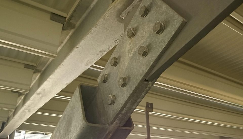
When considering load transfer, we start by establishing the load path: how forces pass from one structure to another and onwards into the building's load-bearing elements. The connection must match the assumptions made in the structural scheme, as rigid, pinned and sliding connections behave differently under load and also affect adjacent structures. If the fixing shown on the drawing does not match the analysis model, both the distribution of forces and structural deformation may change. The way the connection works must therefore be shown alongside the required dimensions, materials and fixing conditions. Simply naming a fastener is not enough to assess the load-bearing capacity and stiffness of the connection as a whole.
When checking a connection, it must be considered as a whole, rather than focusing only on the strength of an individual bolt, anchor or weld, because forces also pass through the surrounding materials. The governing factor may instead be failure of the base material, proximity to an edge, bearing pressure at the contact surface or local bending of the connected component under load. The arrangement of fixings and the eccentricity of the load relative to the connection also affect force distribution, so fixings cannot always be assessed individually. We emphasise that the suitability of a fixing must be assessed against the actual substrate and service conditions. The necessary checks and the assumptions on which they are based form part of the structural design.
Loads do not always act on a connection in the same way, so it is important to distinguish between in-service conditions, erection and other load cases covered by the design. A partially completed structure may lack supports or bracing elements that provide the building with its final stability only after subsequent stages of work. A connection that is adequate for the completed building may therefore not ensure safe installation before all related parts are connected. We recommend specifying in the design when the connection begins to carry loads and which conditions must be met before it does so. Where necessary, the temporary support arrangement and the conditions for its removal must also be defined.
Allowing for movement in different materials
When connecting different materials, we allow for the fact that their dimensions and shape may change at different rates and to different extents, even under the same environmental conditions. Temperature changes, fluctuations in moisture content, concrete shrinkage and long-term creep can cause incompatible deformations at the connection if it restrains them. Moisture movement in a timber component, for example, cannot be treated in the same way as thermal expansion of a metal fixing, because the causes and directions of movement differ. If the connection prevents necessary movement, additional stresses, cracks or damage to finishes may result. Movement requirements must therefore be established before the final selection of fixings and joint fillers.
A connection that accommodates movement does not mean a structure that moves uncontrollably, but clearly defined freedom in the required direction while maintaining the necessary restraints. The detail must distinguish between displacements or rotations that are permitted and those that must be restrained to ensure the building performs as designed. This may require a sliding surface, a slotted fixing hole or a separate movement joint, but the choice must be based on the structure’s calculated behaviour and service conditions. We recommend showing the direction of movement on the drawing and describing how load transfer is maintained at the same time. Otherwise, a component intended to allow movement may inadvertently be fixed rigidly during installation.
When designing movement allowances, it is important to distinguish between material deformation in service and dimensional deviations arising during construction, as these serve different purposes in a connection. The installation clearance may be used up in fitting the structural elements together, leaving insufficient room for the intended movement even though the components appear to fit. Joint seals, flashings and finish layers must also be able to accommodate movement in the connection without restricting its function or suffering damage themselves. We therefore check movement capacity across the entire detail, not just at the connection between load-bearing components. Accounting for differences in material behaviour also provides a basis for carefully detailing the continuity of subsequent layers.
Ensuring thermal and moisture-control continuity
We check insulation continuity in section through the junction, tracing the insulation layer from one building element to the next and identifying interruptions at fixings. Where insulation is interrupted by a load-bearing component, a fixing or a change in geometry, the resulting thermal bridge and internal surface temperature must be assessed. Simply adding thicker insulation to an adjacent surface may not resolve the local weakness or prevent moisture accumulation. Where necessary, the detail’s performance must be verified with a thermal transmittance calculation that accounts for its actual geometry and materials. The design must also show how insulation will be installed without gaps, including in hard-to-reach areas.
We treat airtightness and moisture performance as separate tasks, although their solutions often sit alongside each other within a detail and affect one another. Connections in the air barrier must prevent moist indoor air from entering the building assembly, while the water vapour resistance of the layers must be compatible with the assembly’s ability to dry. The need for a vapour barrier and its position cannot be determined from a material’s name alone, as the entire build-up is decisive. The use of the space, indoor climate, external environment and full assembly build-up must all be considered, including potential sources of moisture. Particular care is needed when detailing transitions to windows and doors, penetrations and surfaces with differing water vapour resistance.
In a detail exposed to the outdoor environment, we distinguish between keeping rainwater out, draining incidental water and allowing the assembly to dry, as each serves a different purpose. A seal should not be the design’s only line of defence if moisture can accumulate behind it with no means of escape. The design shows the water flow path, the necessary falls and connections to flashings, membranes and drainage openings so that water is not directed into the assembly. We also check that movement at the junction will not close gaps needed for drying or drainage, or tear the seal open. Here, material compatibility also includes adhesion, substrate condition and the suitability of seals for the intended environment.
Fire resistance and sound insulation requirements
We treat fire resistance as a property of the entire junction, not of an individual board, foam or seal, because fire affects the complete assembly. Where a detail lies on a fire compartment boundary, the connection must maintain the fire resistance required by the design, including where movement and penetrations occur. This requires a solution whose conditions of use match the actual substrate, joint width and installation orientation, rather than a choice based solely on the product name. Product documentation is checked for requirements including fill depth, backing and permitted joint movement to substantiate the use specified in the design. A general note calling for fire-resistant filling does not give the contractor a sufficient basis for constructing or inspecting a compliant detail.
For sound insulation, we consider not only direct sound transmission but also transmission along adjoining structures and through their connections. A wall with good sound insulation may perform below expectations if sound bypasses it through a shared ceiling, floor or rigid connection. A resilient interlayer can reduce vibration transmission, but its load-bearing capacity and deformation must remain compatible with the structure’s behaviour throughout its service life. Air leaks must also be avoided, as even a small open connection can significantly reduce the sound insulation of the entire separating element. We therefore define both the sealing approach and the connection stiffness requirements in the detail.
Fire resistance and sound insulation requirements must be met within the same junction detail without one compromising the other. A flexible filler suitable for acoustic purposes may not be suitable for a fire-resistant joint, while a fire-resistant seal may not provide the required sound insulation. The choice must be based on the verified limits of use of the solution, not on an unsupported assumption that the properties of different products can simply be combined. For service penetrations, connections involving pipes, cables and supports must also be specified, as both sound and fire can spread through them. Subsequent changes must be assessed against the same requirements rather than treated solely as installation matters.
Checking the buildability of junction details in the design
When checking buildability, we review the junction in construction sequence, not just as a section through the finished structure with all layers in place. For each layer, it must be clear when it will be installed and whether the relevant surface will still be accessible at that stage. A connection may work on paper but prove impossible to build if a fixing point is covered before the next component is installed or sealed. Space must also be allowed for tools, compressing the seal and inspecting the connection before it is enclosed by other construction layers. Where necessary, a complex junction requires a separate installation diagram explaining the sequence of operations and any temporary support.
We check dimensional compatibility alongside construction tolerances, as an actual joint never matches the ideal geometry of the drawing at every point. The permitted joint width must accommodate both installation deviations and the intended movement without compromising the seal or fixing. Adjustment must be provided for through designed components, rather than left to improvised packing or the enlargement of holes on site without a technical assessment. It is particularly important to coordinate the reference surfaces and dimensions for different work packages before ordering products and preparing openings on site. If the dimensions of the existing structure are uncertain, they must be verified before the final junction detail is approved.
The design specification for a junction must bring together the drawing, material requirements and installation conditions in a single, clear package that can be used to organise the work. Simply naming a product is not enough if substrate preparation, the fixing method or the permitted movement of the connection in service remains undefined. We also check that the architectural, structural and building services designs do not give conflicting instructions for the same joint in different drawings or specifications. Responsibilities must also be clear where a layer installed by one contractor connects to a structure built by another. Unresolved issues must be clarified with the designer before work begins, rather than covered by a general note to make adjustments on site.
- Installation sequence and access to connections
- Tolerances and adjustment options
- Compatibility of materials and seals
- Consistent instructions across design disciplines
Key takeaways
-
Loads and movement The joint must carry the specified loads and accommodate differential movement between materials without compromising the connection's performance.
-
Meeting requirements together Thermal insulation, moisture performance, fire resistance and sound insulation must be addressed together, as improving one property can affect the others.
-
A buildable design The junction drawing must account for installation sequence, access and tolerances, and provide consistent instructions for the different work packages.
This article is for general information only and does not replace professional advice.